Robotic Crane
ME 380 | 2023
Objective: Design and fabricate a device that smoothly transports ferromagnetic objects of complex geometries from a pickup location to two distinct drop-off locations at varying heights. The device must be built within a $300 budget, and in a team of 5 people.
Overall Project Summary

High-Level Overview
Following conceptual design, a crane-like structure was decided upon to meet the aforementioned criteria. This design was split up into three main assemblies; rotational, vertical, and radial. Between these three motions, the device is able to pickup and drop-off objects anywhere within its maximum and minimum radii.
-
Rotation about the Z axis is provided by a pinion and ring gear within the base, which rotates the top part of the rotational subassembly (green part), and subsequently the rest of the structure above it.
-
Vertical motion is provided by a lead screw that protrudes from a motor, fastened to the rotational subassembly.
-
Radial motion is induced by a rack and pinion that is connected to a rolling cart (orange part), which sits atop the vertical subassembly.
-
An electromagnet is used to grasp and release objects.
Personal Contributions
-
Designed the Rotational Base subassembly
-
Fabricated 50% of the 3D printed parts for the entire design.
-
Assembled the rotational base and assisted with assembling the rest of the design.
-
Collaborated with teammates on mechanical design decisions.
-
Scheduled and led team meetings.
Technical Summary of Personal Designs
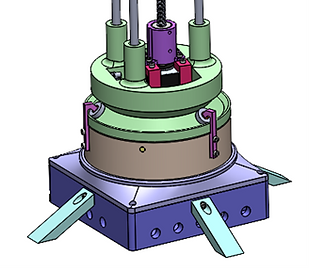
Rotational Support System
The most compelling feature of this design is the rotational support system, which allows rotation about the Z axis, while constraining the other 5 degrees of freedom. This mechanism is comprised of 4 main components;
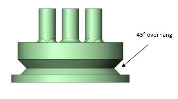
1. Rotary component (green part)
-
DFM such that it can be 3D printed with zero supports- indented area that interfaces with the bearings is specifically designed at 45º for one of two reasons, this being one of them.
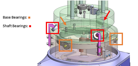
2. Bearings
-
Allow for rotation while constraining radial forces- a total of 6 bearings are utilized to securely constrain 5 degrees of freedom;
-
Base Bearings (QTY 3)- provide a normal force to constrain translation in Z, while still allowing for rotation
-
Shaft bearings (QTY 3) – provide constraining forces in X and Y to restrict any movement other than rotation about Z.
3. Bearing Shafts
-
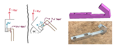
DFM with 2D geometry such that it can be waterjet cut (the thru holes were milled)- this component is manufactured from aluminum instead of 3D printed plastics, as it will undergo greater forces, induced by the moment that the arm and electromagnet impose on the base.
-
Designed to interface with the rotary component at 45º to distribute the forces, minimizing the shear force experienced by the shaft.
4. Bearing Adapter
-
Circle-to-square adapter to connect the 2D rectangular bearing shafts to the circular inner ring of the bearing.

Rotational Motion
A motor housed within the rotational base subassembly meshes with a ring gear to facilitate the rotation about Z. This mechanism is comprised of 2 components;
1. Motor Gear
-
Utilized a 5:1 gear ratio to increase torque output and overcome inertia of the top assembly.
-
Designed for maximum possible height within the bounds of the assembly to increase contact area and reduce the forces experienced by each individual tooth.

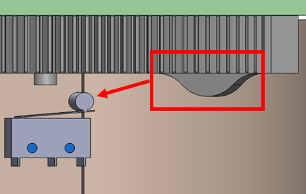
2. Ring Gear
-
Implemented a ‘bump’ to trigger a limit switch for homing purposes.